NEC Network and Sensor Systems,Ltd.
Breadcrumb navigation
Principles and Fundamentals
Microwave tubes used in satellite communications and troposcatter communications systems are mainly TWTs (Traveling Wave Tubes) and klystrons. These are vacuum devices which amplify microwaves by converting the kinetic energy of an electron beam into microwave energy.
TWTs are mainly classified into two types, helix TWTs and coupled-cavity TWTs, according to the RF circuit structure. The fundamental construction of helix TWTs, coupled-cavity TWTs and klystrons are shown in 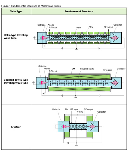 Figure 1 Fundamentals-Structive of Microwave Tubes. The electron gun, the collector and the electron beam focusing structure are common elements to all of these tubes. The RF circuit for converting energy is different in each case. Slow-wave circuits such as a helix or coupled-cavities are used in TWTs, whereas, several resonant cavities are used in klystrons.
The operation of a TWT is as follows: Electrons emitted from the cathode are accelerated by a potential difference between the cathode and the anode. An electron beam is formed and focused in the electron gun region to be injected into the slow-wave circuit where it interacts with the propagating RF wave. The axial phase velocity of the RF wave is delayed by the slow-wave circuit such that it is almost the same velocity as the electron beam. Upon injection into the input section of the RF circuit, the electron beam is velocity-modulated. As it passes through the RF circuit, the velocity-modulation in the electron beam changes gradually to density-modulation, and then induces an amplified RF wave at the output section of the slow-wave circuit. The role of the RF attenuator placed in the center portion of the slow-wave circuit is to prevent feedback oscillation in the TWT. After passing over the slow-wave circuit, the electron beam reaches the collector, and the electron energy is converted to heat and dissipated.
The operation of a klystron is as follows: The electron beam is velocity-modulated by the RF field in a gap of the input cavity. As the electron beam passes through the drift region, where the RF wave does not exist, the electron beam is converted from a velocity-modulated state to a density-modulated state. The intermediate cavities enhance the electron beam modulation, then an amplified RF signal is induced at the final cavity. The resonant frequency of each cavity is staggered a small amount in order to enlarge the instantaneous bandwidth of klystrons. A pre-set tuning mechanism is installed in some klystrons to change channels quickly to save customers the extra task of channel tuning.
As for the electron beam focusing structure, PPM (Periodic Permanent Magnet), PM (Permanent Magnet) and EM (Electro Magnet) are used respectively for helix TWTs, klystrons and coupled-cavity TWTs for high power use.
The main difference between the operation of a TWT and a klystron is that while the TWTs' circuit operates in a non-resonant mode, the klystrons' circuit operates in a resonant mode. Therefore, the electronic conversion efficiency is relatively low for TWTs and fairly high for klystrons. Also the instantaneous bandwidth is generally wide for TWTs and very narrow for klystrons.